How To Build A Power Tool Table: Part 3
The Top
Before starting work, it’s strongly advised to thoroughly read and digest the instructions for using the UJK Technology Parf Guide System as well as the excellent video clip made by Peter Parfitt. Although the system initially looks a little daunting, it’s based on a very ancient mathematical principle and once the user understands how it works, it’s child’s play to use. Depending on your requirements, you may not need to produce a complete matrix of holes but in this instance I have done so to show the versatility of the system.
The top is made from 18mm Medite, which is a type of mdf where the two outer layers (each approximately 3mm thick) are extremely dense and the centre section is only slightly less so. From one end of the 8x4, cut off a piece about 760mm long as it will be trimmed to exactly the right width later on. This leaves one dead square end and one side which is roughly cut; thus the dimension of the top to start with is 1220x760mm.
The position of the very first hole is absolutely critical, as it’s this that determines the position of all the others. If it’s not correct, then the final matrix of 20mm holes may foul parts of the framework. The position of this hole is shown with an asterisk on the working drawing.
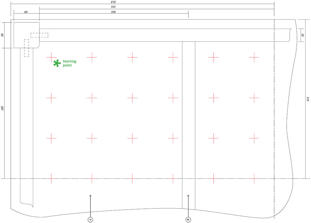
Along the 760mm dimension measure 87mm from one of the right angle corners and draw a line with square and pencil perpendicular to the edge. Repeat this process on the longer 1220mm edge but this time measure 82mm and where the two lines intersect is the position (arrowed) of the first hole.
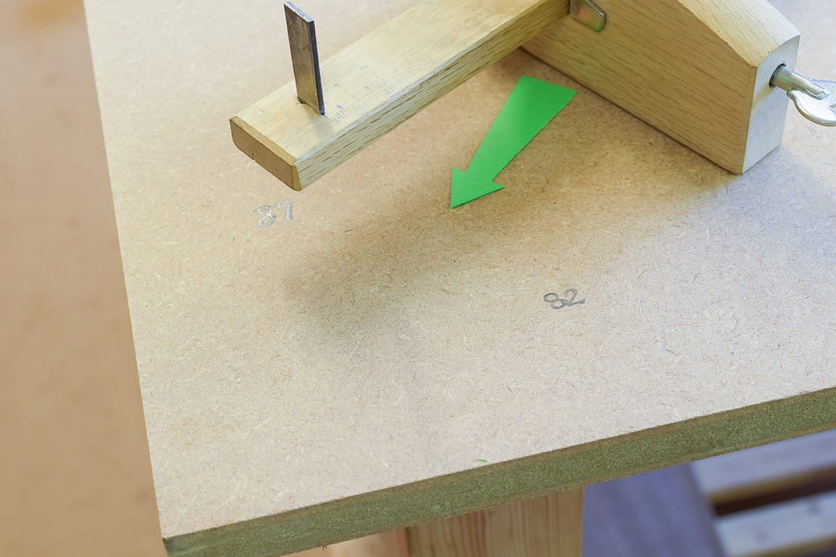
Position a 3mm hole on one of the Parf Sticks directly over the mark, cramp the Parf Stick in place and use the 3mm drilling guide to make the first hole.
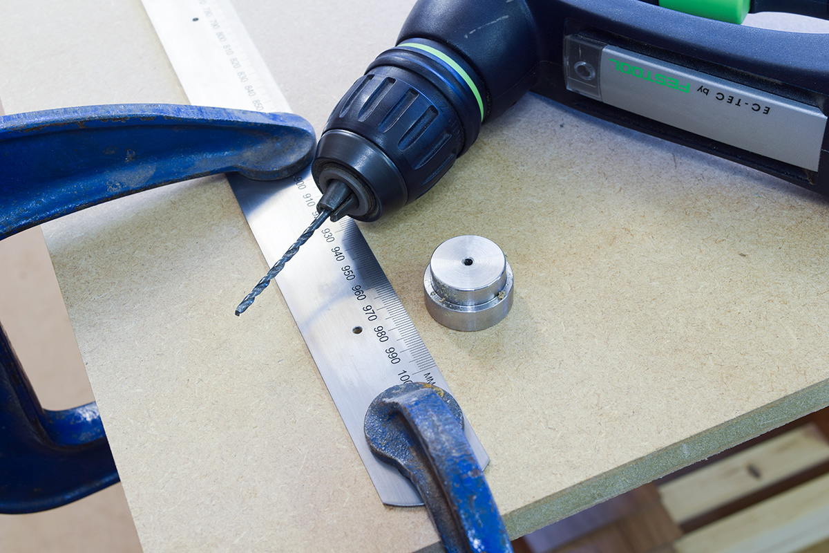
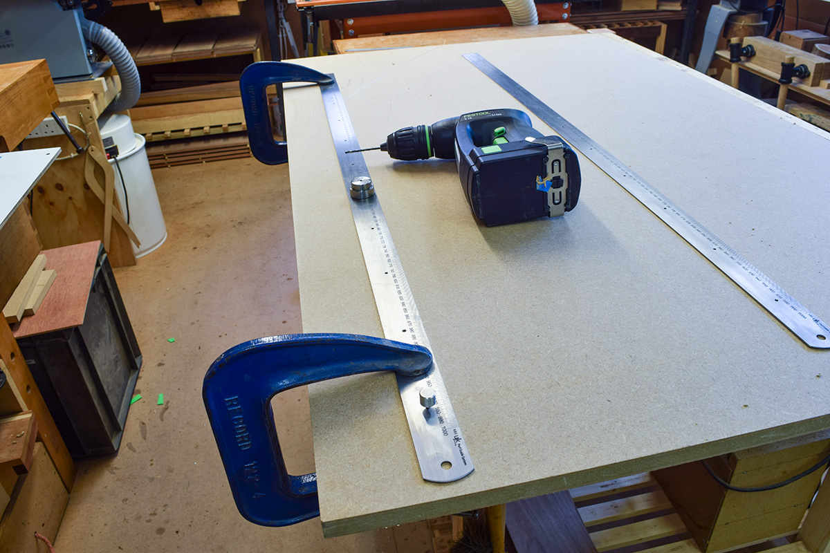
Using a 3mm pin, position the Parf Stick parallel to the long edge of the top, clamp in place and drill the remaining 3mm holes along that side, thus completing the first line of holes.
Carefully following the instructions, rotate the first stick through 90°. Position and pin the second Parf Stick six units away from the initial hole, pinning the second Parf Stick at the eighth unit on the first stick forming a 6:8:10 right angle triangle.
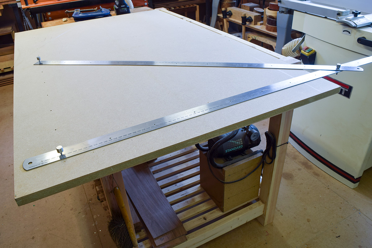
The series of 3mm holes down the short side can now be drilled, completing one side of the board
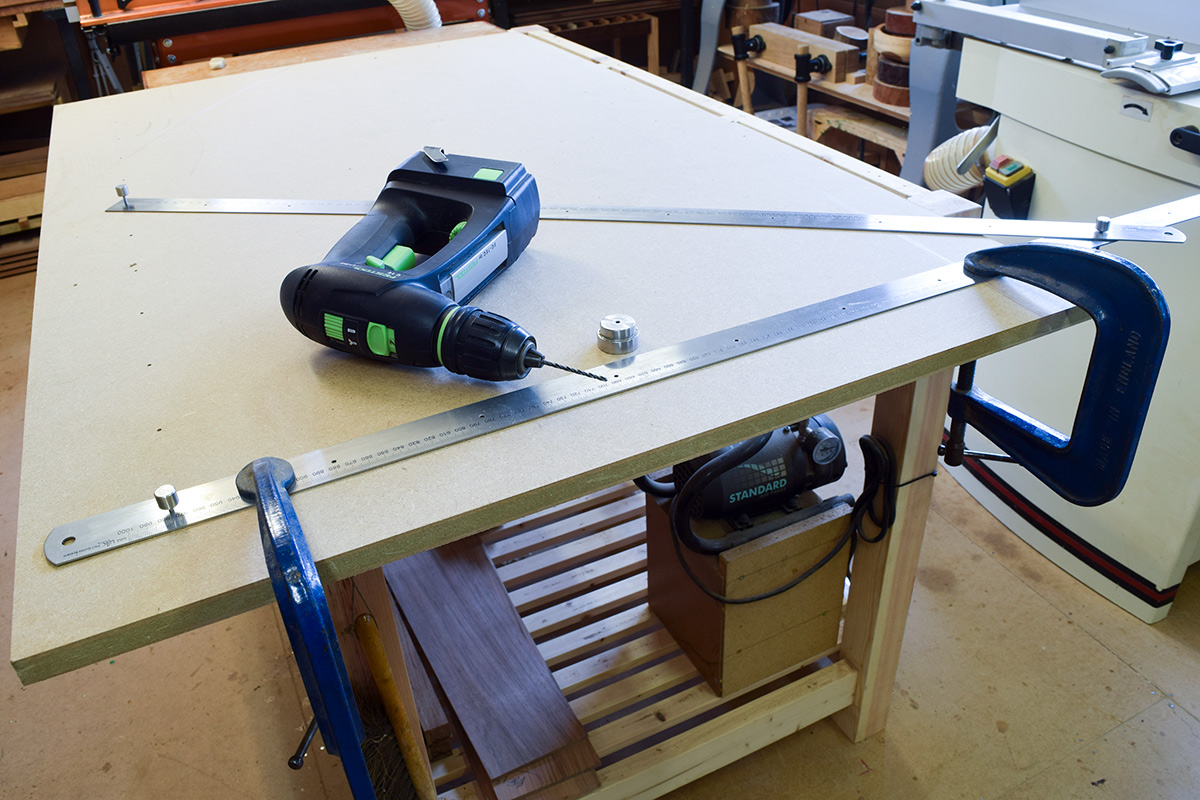
and exactly the same procedure is adopted at the other end to form a ‘hollow box’ pattern of 3mm holes. Complete the fourth side of the box by pinning a Parf Stick to the last two holes; if your work has been accurately set out, the Parf Stick will drop directly over them and enable the the remaining 3mm holes to be drilled.
Complete the required matrix of 3mm holes in the top after which the Parf Sticks can be stored safely in their plastic covers for use on another day.
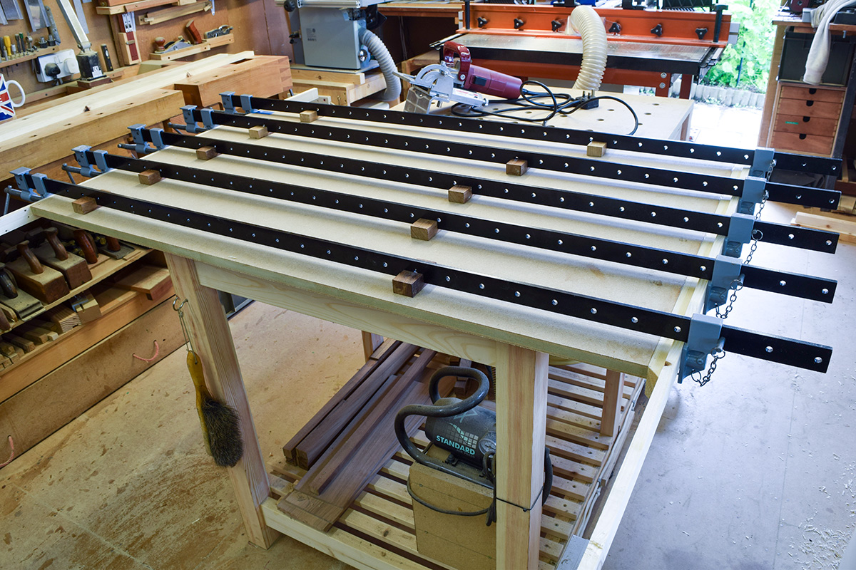
The next step is to enlarge each 3mm hole to 20mm using the special drilling jig and boring bit supplied with the kit. It’s an excellent idea to lubricate the drill bit
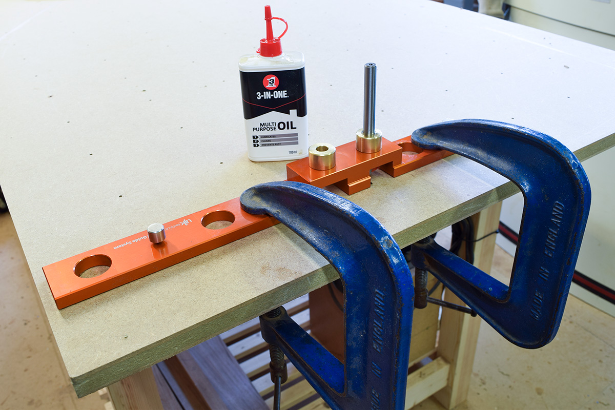
occasionally, especially when changing from one bush to another. Although unnecessary, I oiled the shaft for each hole drilled with the result that the top became smeared with oil residue which looks untidy but is of no real consequence.
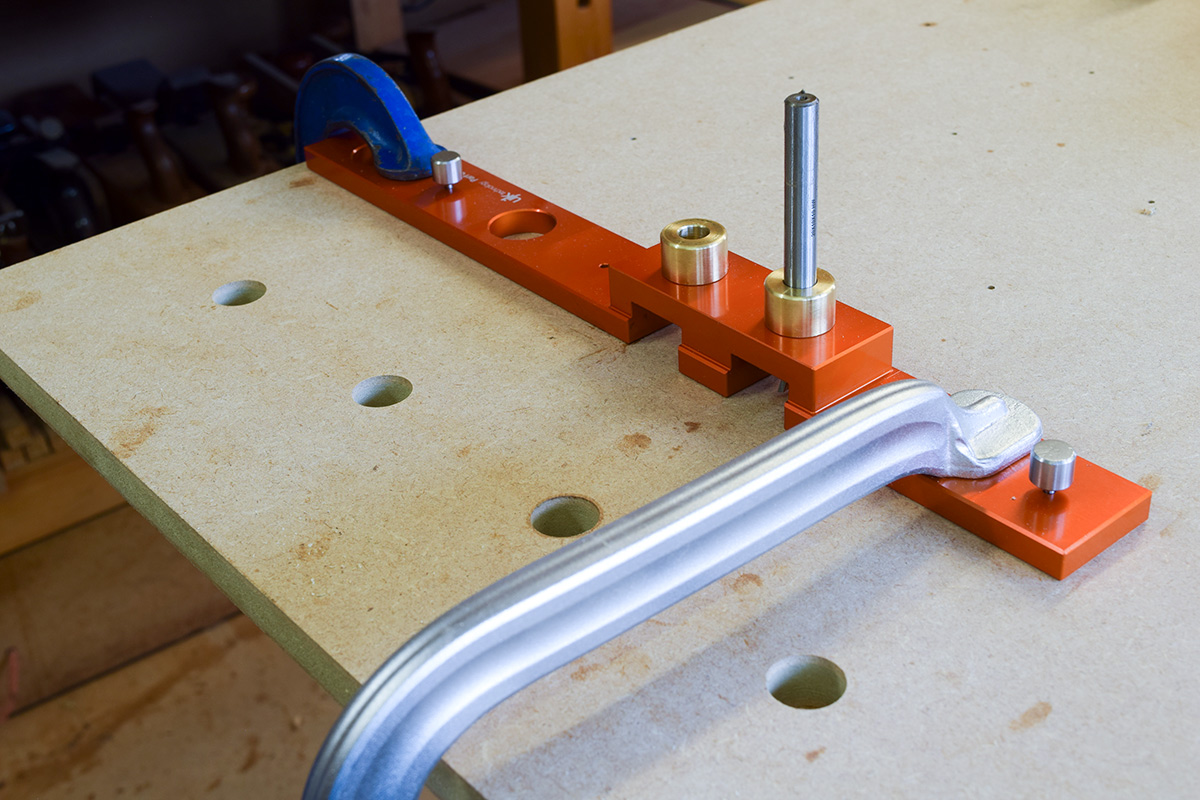
To ensure accuracy and that the drill bit doesn’t move, clamp the drilling jig to the top, either with a range of G or F clamps or with Veritas Bench Dogs. Make sure also that the Bench Dogs are securely held from the underside with Clamping Knobs or even ‘shop made knobs as shown.
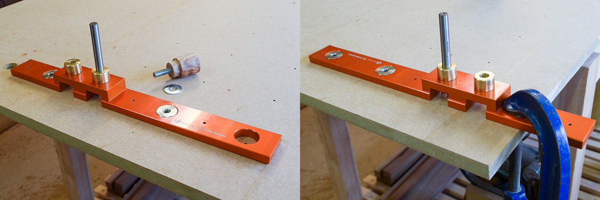
With some of the holes in the middle of the board, it may not be possible to apply additional clamping to the jig, in which case, it must be held in position by using just a couple of 3mm pins.
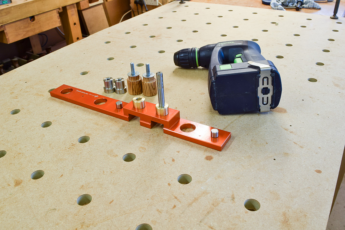
Once each 20mm hole has been drilled, the bit can be removed by withdrawing through the board from the underside. It’s imperative that the bit is NEVER dropped onto a hard workshop floor. I took the precaution of placing a thick, old door mat directly underneath and, even so, I managed to drop the bit twice, but fortunately onto the mat each time!
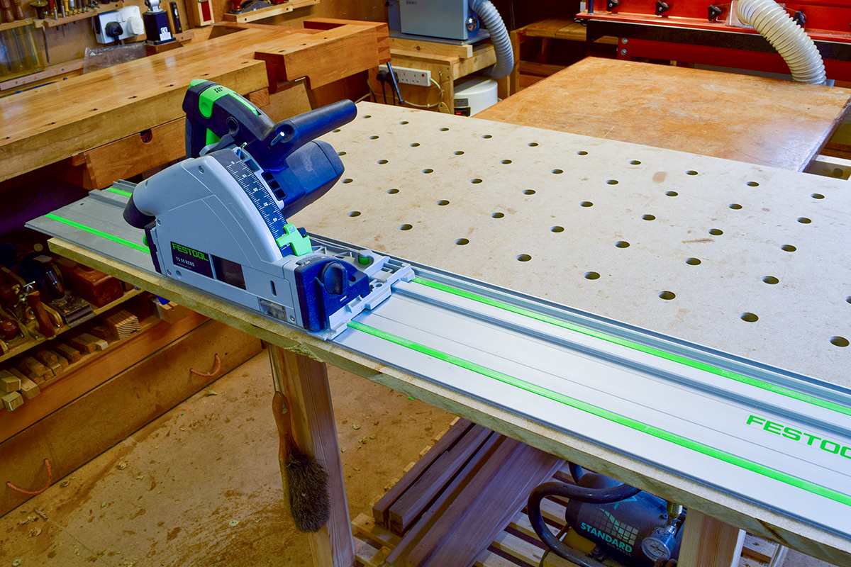
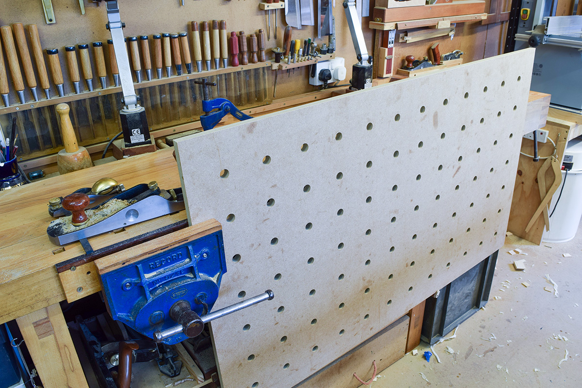
Once the pattern of 20mm holes has been completed, the top is cut exactly to size (750mm) using a track saw and rail.
The Cover
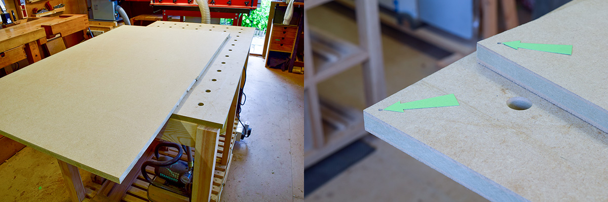
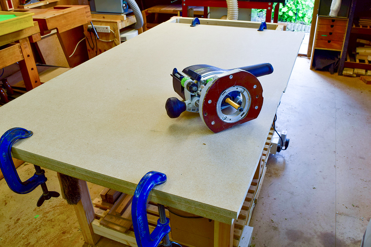
The cover is a close fit over the top and is made from another piece of Medite, again cut to around 760mm wide. Dots are used to provide a reference corner (arrowed) and then both are accurately clamped together so that the two long edges can be bearing cut with a router.
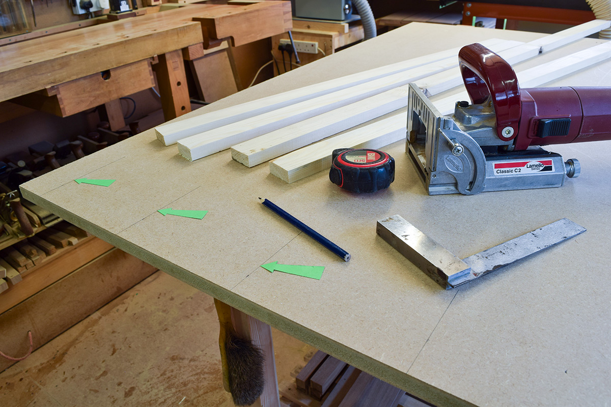
Prepare some lengths of pine lipping, allowing sufficient to be planed off underneath for a flush fit, then mark out the positions for the biscuits (arrowed) or Dominos if preferred.
Mitre the corners and glue the lipping to the edge one section at a time, ensuring that all traces of glue squeeze-out is removed from the underside. If it’s not, there may be difficulty in fitting the cover over the top.
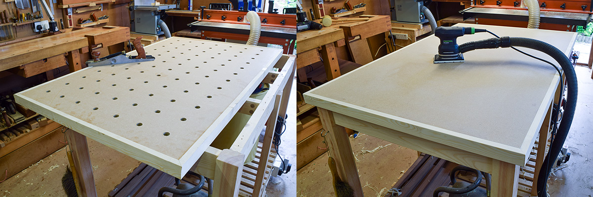
Once the lipping has set, plane the edges of the top, taking a few passes each time until it’s a close, sliding fit onto the cover.
The image shows the top upside down (ie. cover underneath) so that the lipping can be planed flush with the underside after which the top is screwed accurately in place on the framework, the cover fitted and then sanded smooth. To provide a glue resistant finish, two coats of Osmo PolyX are applied followed by generous application of wax.
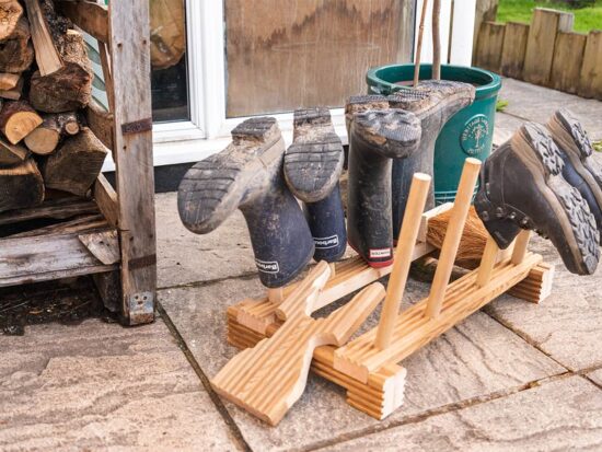
The addition of this Power Tool Table to the workshop now provides me with a large, flat surface for assembly and gluing. As an added bonus, the removal of the cover means that with my track saw, it’s now far easier, quicker and accurate to prepare sheet materials.